
Bridging the Vertebrae: How Spinal Cages Restore and Fuse the Human Column
Updated: Aug 17
Post Written By: Naseer Ali
Abstract
Spinal cages have revolutionized reconstructive spine surgery, evolving from simple structural spacers into highly engineered, bio-functional implants. This educational article provides a systematic, end-to-end overview of spinal cages across all vertebral segments—cervical, thoracic, and lumbar. It examines the underlying biomechanical requirements of spinal fusion, details anatomical considerations across surgical approaches, evaluates material performance (including titanium alloys, PEEK, HA-PEEK composites, and bioabsorbable alloys), and analyzes current market trends in additive manufacturing, 3D printing and patient-specific cage customization.
Introduction: What is a Spinal Cage?
When conservative treatments fail to relieve severe neck or lower back pain, surgeons may recommend spinal fusion—a procedure designed to permanently connect two or more vertebrae. A central component of this surgery is a device known as an interbody cage or commonly known as spinal cage. During surgery, the damaged disc is removed. Inserted directly into the space between the affected bones, this small, hollow implant acts as a structural spacer to maintain natural disc height and stabilize the spine. Over time, natural bone tissue grows through the cage, ultimately fusing the vertebrae together into a single, solid bone structure. It eliminates painful motion and provides permanent spinal stability.
Interbody fusion cages play a critical role in modern spinal reconstruction by replacing damaged or degenerated intervertebral discs, restoring healthy disc height, and creating a stable environment for bony fusion. The structural layout of the human vertebral column across the cervical, thoracic, and lumbar segments, alongside the targeted placement of an interbody fusion cage within the intervertebral disc space, is depicted in Fig. 1.
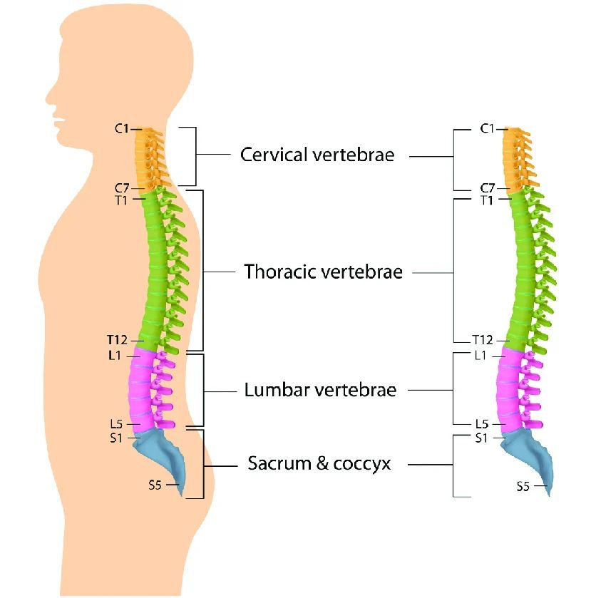
Fig. 1 Anatomical diagram of the cervical, thoracic, and lumbar regions of a human spine [1].
When intervertebral discs degrade due to degenerative disc disease (DDD), spondylolisthesis, trauma, or deformity, the intervertebral height collapses. This collapse leads to severe mechanical instability, spinal alignment loss (loss of lordosis or kyphosis), and neural impingement [2].
An interbody fusion cage (or spinal cage) is a specialized biomedical implant designed to be inserted directly into the disc space following a discectomy [3], [4]. Its core purpose is twofold:
1. Immediate Structural Support (Mechanical):
Restores lost intervertebral disc height, re-establishes natural spinal curvature, and instantly decompresses pinched spinal nerves [2], [4].
2. Long-Term Biological Fusion (Osseointegration):
Serves as a hollow scaffold packed with bone graft material (autograft, allograft, or synthetic bone morphogenetic proteins) to allow living bone cells to bridge adjacent vertebrae, fusing them into a single continuous structural bone [3], [4].
To achieve stable spinal fusion, the implant must maintain mechanical integrity while facilitating long-term osseointegration. Modern interbody fusion cages feature specialized geometric structures, including a large hollow central chamber designed for bone graft packing and textured surface serrations or teeth to prevent post-operative displacement (Fig. 2). These design elements work in tandem to optimize load distribution across the intervertebral space while providing immediate primary stability against movement during early healing phases.

Fig. 2 Anatomical diagram of a lumbar spinal cage [5].
Biomechanical Mechanisms and Objectives
Spinal cages operate under intense, cyclic biomechanical loads ranging from several hundred Newtons in a resting state to over 2000 N during bending or heavy lifting [4]. To achieve clinical efficacy, cage design balances three primary objectives:
1. Neuroforaminal Decompression and Sagittal Alignment:
When a spinal disc collapses, the small openings where nerves exit the spine become pinched and narrow. By inserting a cage with a tailored height and angled wedge (such as a 4° to 15° slope), the surgeon re-opens these nerve pathways, relieving pressure on squeezed nerve roots and restoring the natural, healthy curve of the spine [2].
According to a clinical study by Batra and Ghosh (2024) [7], the surgical technique for the dual-incision mini-open TLIF procedure progresses through a structured sequence. This progressive decompression and alignment sequence is illustrated in Fig. 3.
Patients lie face-down while asleep under anesthesia. Using real-time X-ray imaging, the surgeon locates the exact spot on the spine and makes two small cuts 3.5 cm to the side of the spine's center (Fig. 3A). Cutting off to the side—rather than straight down the middle—protects the main back muscles from being cut through or damaged.
Special tube-like tools are gently inserted through the muscle to create a clear visual path down to the backbone (Fig. 3B). Small metal screws (pedicle screws) are then placed into the vertebrae on one side to act as anchors, while electrical sensors continuously monitor the surrounding nerves for safety [7].
The surgeon then moves the viewing tube over the other side to access the pinched nerve. Using a microscope and a tiny drill, they trim away any bone or tissue squeezing the nerve, clear out the damaged spinal disc, and gently stretch the space back to its original healthy height (Fig. 3C) [7].
To keep the bones permanently separated and encourage them to fuse together, a small hollow spacer called a "cage"—packed with natural bone material—is inserted directly into the emptied disc space (Fig. 3D) [7].
Finally, screws are placed on this second side as well. Metal rods are locked onto all the screws, binding the spine securely in place so it can heal as one solid, stable structure (Fig. 3E).
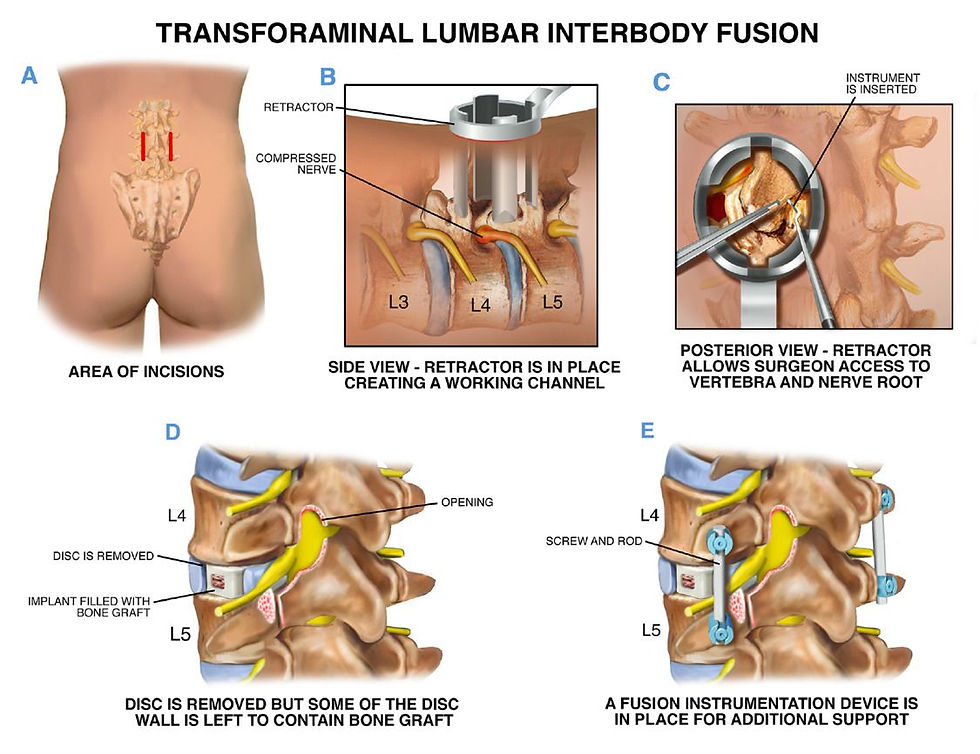
Fig. 3 Simplified mechanical representation of an interbody cage restoring disc height and relieving pressure on spinal nerves in L4-L5 lumbar spine [7].
2. Primary Mechanical Stability (Anti-Expulsion):
Before biological bone fusion occurs (which takes 6 to 12 months), the cage must rely on primary mechanical friction to prevent migration or expulsion [4], [6]. Cages achieve this interlock through textured endplate teeth, pyramidal ridges, or integrated fixation screws that bite into the vertebral subchondral bone [2], [6].
3. Load Sharing vs. Stress Shielding:
According to Wolff’s Law, bone remodels and strengthens in response to physical stress. If an implant is excessively rigid (such as solid titanium alloys with an elastic modulus E ≈ 110GPa), it absorbs virtually all compressive forces. This phenomenon, called stress shielding, deprives the central bone graft of natural stress, leading to localized bone resorption and implant loosening. Conversely, if a cage is too soft, it collapses under load. Hence, modern cages are designed to closely match the elastic modulus of human cortical bone (E ≈ 15 - 18GPa) [4], [6].
Taxonomy of Spinal Cages Across the Entire Spine
While lumbar cages are the most widely discussed spinal implants, interbody fusion cages are actually utilized across every moveable segment of the vertebral column. Each spinal region imposes its own distinct geometrical, mechanical, and anatomical constraints on implant design and deployment [2],[3].
To account for these varying requirements, the spine is divided into specific structural sections: the cervical spine in the neck, the thoracic spine in the mid-back, and the lumbar spine in the lower back, followed by the sacrum and coccyx at the base. Because bone size, weight-bearing load, and range of motion change drastically from the neck down to the lower back, cages must be engineered specifically for the target region's anatomy. This complete regional division of the human backbone is illustrated in Fig. 4.
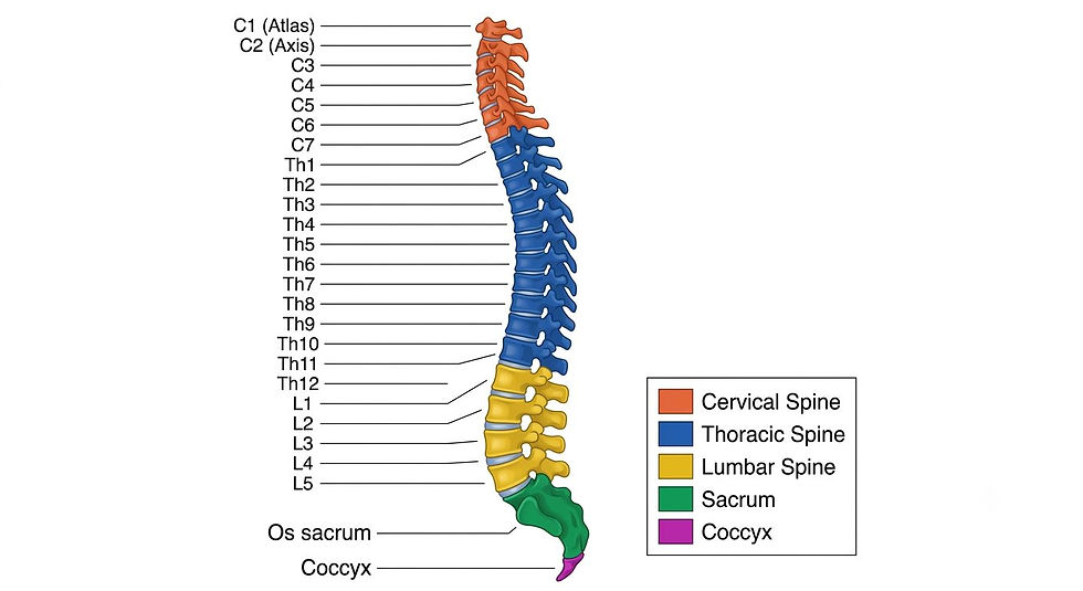
Fig. 4 Anatomical division of the human vertebral column [8].
1. Cervical Interbody Cages (C3–C7 Segment):
Cervical interbody fusion cages are offered in a range of standardized dimensions designed to accommodate individual anatomical variations across patient populations. In terms of lateral footprint, the cage width (left-to-right) typically spans from 14 to 17 mm, with 14 mm, 15 mm, and 16 mm being the most common configurations. The depth (front-to-back) ranges between 11 and 15 mm, commonly utilized in 12 mm or 14 mm options to properly cover the anterior-to-posterior length of the cervical endplate. To restore proper intervertebral clearance, cage height varies from 4 to 10 mm, adjustable in 1 mm increments, though heights between 5 and 7 mm are most widely indicated for standard cervical disc spaces. Additionally, to help maintain or correct natural cervical alignment, these cages feature built-in fixed lordotic angles ranging from 5° to 12° [9].
Cervical Interbody Cages are usually box-shaped, anatomical saddle-shaped, or trapezoidal configurations [2]. Stand-alone cervical cages feature built-in zero-profile screw holes that allow internal screws to anchor directly into the upper and lower vertebral bodies, eliminating the need for bulky anterior cervical plates [2], [4]. These structural geometry variations and integrated fixation features of cervical interbody implants are illustrated in Fig. 5.
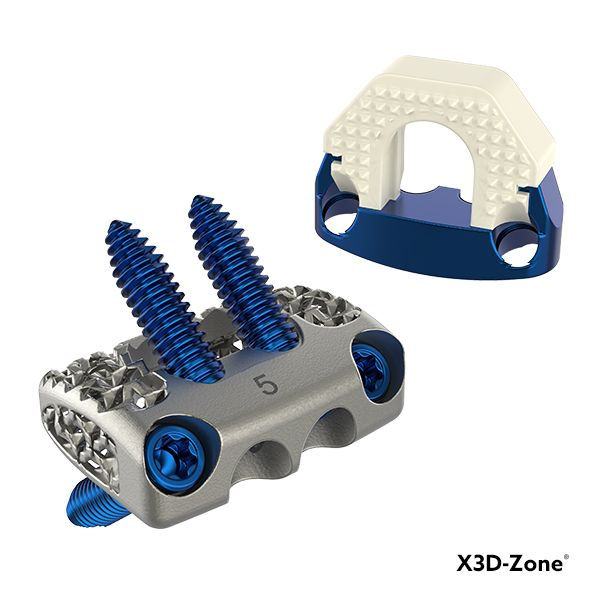
Fig. 5 3D-printed titanium and PEEK cervical interbody fusion cages.[10].
2. Thoracic Interbody Cages (T1–T12 Segment):
Thoracic interbody cages feature specialized geometries tailored for safe insertion through restricted anatomical corridors. To prevent damage to nearby nerve roots and the spinal cord, their width is kept relatively narrow at 10–14 mm, while depth ranges from 20 to 30 mm and height spans 6–12 mm. Because the thoracic spine possesses a natural kyphotic curvature, these implants typically incorporate minimal sagittal correction—featuring parallel 0° profiles or mild angles between 0° and 5° depending on the targeted segment and surgical approach. Structurally, they are frequently crafted into bullet-shaped or curved "banana" geometries, which facilitate smoother passage past delicate neural structures during delivery via posterior or transforaminal (PLIF/TLIF style) and lateral surgical corridors.
The proximity of the spinal cord, rib cage, and vital vascular structures (aorta, vena cava) makes open thoracic approaches high-risk. Thoracic cages are often deployed via mini-open posterolateral or transthoracic lateral approaches, frequently using expandable cage technologies [3].
To ensure the implant is both strong enough to support the spine and gentle enough to insert safely, thoracic cages are frequently made from advanced biocompatible plastics. As shown in Fig. 6, these implants feature specialized outer contours, endplate-gripping ridges, and radiolucent materials suited for tight thoracic spaces. These plastics closely match the natural flexibility of human bone and do not block X-rays or CT scans, allowing doctors to clearly monitor healing after surgery.
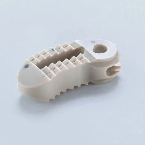
Fig. 6 PEEK thoracic spinal cage [11].
3. Lumbar Interbody Cages (L1–S1 Segment):
Although lumbar cages are frequently the primary focus of literature, interbody devices are deployed throughout all mobile segments of the spine. Consequently, each anatomical region presents unique structural, biomechanical, and spatial requirements [2].
A. Anterior Lumbar Interbody Fusion (ALIF):
Placed directly through the abdomen, Anterior Lumbar Interbody Fusion (ALIF) cages feature a large trapezoidal footprint measuring 30–40 mm in width, 24–30 mm in depth, and 9–17 mm in height. This substantial surface area maximizes stability against axial loads and prevents cage subsidence. Furthermore, ALIF implants incorporate steep built-in lordotic angles ranging from 8° to 20° (Fig.7) to actively restore natural lumbar lordosis at lower spinal levels [12], [13]. These devices also utilize a hollow central core filled with bone graft material to accelerate biological fusion between adjacent vertebrae, while external surface teeth or integrated fixation screws provide immediate primary stability against movement.
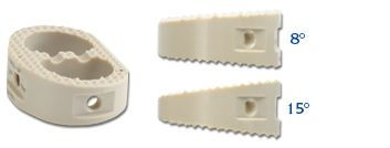
Fig. 7 ALIF Lumbar Spinal Cage [13].
B. Lateral and Oblique Lumbar Interbody Fusion (LLIF / OLIF):
Lateral (LLIF) and Oblique (OLIF) cages are engineered to span the entire width of the vertebral body, resting directly on the dense, rigid apophyseal outer ring to minimize the risk of endplate penetration. These implants feature wide profiles measuring 40–60 mm in length, 16–22 mm in depth, and 8–14 mm in height, with moderate lordotic restoration between 6° and 12°. While LLIF accesses the disc space directly through the psoas muscle, OLIF utilizes an anterior-to-psoas trajectory to preserve neural structures within the retroperitoneal space [14].
To keep the spine steady without requiring extra metal plates, modern oblique implants use built-in anchors like deployable blades or angled screws (Fig. 8) that lock directly into the surrounding bone. Additionally, their surfaces are designed with rough or porous textures that help bone cells attach quickly, encouraging strong, natural healing across the wide footprint.
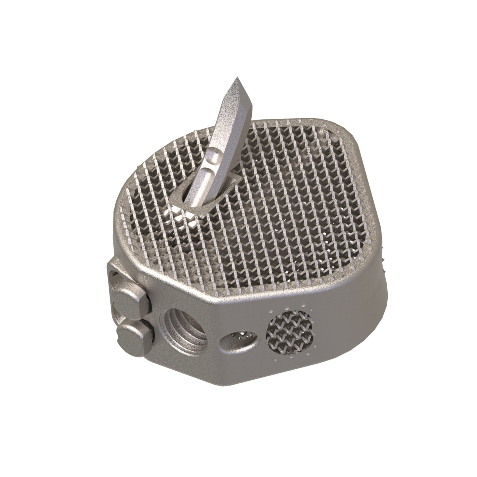
Fig. 8 OLIF Oblique Lumbar Spinal Cage [15].
C. Posterior and Transforaminal Lumbar Interbody Fusion (PLIF / TLIF):
Inserted posteriorly through the spinal canal or neural foramen, PLIF and TLIF implants must feature narrow widths (9–12 mm) to safely slide past the cauda equina and emerging nerve roots. These cages typically measure 24–32 mm in depth and 7–16 mm in height (most commonly 9–13 mm), with lordotic angles ranging from 0° to 15°. PLIF procedures utilize two parallel rectangular cages placed bilaterally, whereas TLIF employs a single curved or "banana-shaped" cage placed obliquely. Both designs frequently incorporate a bulleted nose tip to facilitate self-distraction and smoother entry into tight, collapsed disc spaces [12].
For PLIF procedures, two matching rectangular cages are placed side-by-side (Fig. 9) to provide balanced support across both sides of the disc space. In contrast, TLIF procedures use a single, curved "banana-shaped" cage placed diagonally (Fig. 10), which allows surgeons to achieve proper coverage through a single entry point while minimizing nerve manipulation.
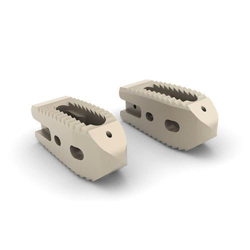
Fig. 9 PLIF Twin peaks Lumbar Spinal Cage [16].

Fig. 10 TLIF Twin Peaks Curved Lumbar Spinal Cage [17].
Classification by Structural Dynamics and Mechanics
Beyond anatomical regions, spinal cages are categorized by their structural motion mechanisms which are divided into two categories, static and expandable cages.
1. Static Cages
Fixed-geometry implants that maintain constant dimensions. They require forceful impaction into the disc space using a mallet, which can risk endplate damage if over-sized [2], [4].
2. Expandable Cages
Advanced dynamic implants inserted into the disc space at a collapsed profile and expanded in situ using internal mechanical gears or threaded drive-screws.
Mechanism: Allows insertion through smaller surgical corridors, minimizing muscle and nerve retraction. Once inside, the surgeon expands the cage vertically (to restore height) and angled (to dial in custom lordosis).
Trade-off: Internal gear mechanisms reduce the central internal volume available for packing bone graft material [3].
Material Science in Interbody Device Engineering
1. Titanium Alloys (Ti-6Al-4V)
Historically, titanium spinal cages have been the gold standard due to superior fracture toughness and biocompatibility.
Pros: Excellent cell adhesion, high mechanical fatigue strength, proven biological track record [4], [6].
Cons: High elastic modulus (E ≈ 110GPa) creates a stark mismatch with bone (E ≈ 15 - 18 GPa), causing stress shielding and increased risk of cage subsidence (sinking into the vertebral body). Titanium also produces heavy metallic artifacts on CT and MRI scans [4], [6].
2. Polyetheretherketone (PEEK)
A high-performance thermoplastic that gained dominance in the early 2000s.
Pros: Elastic modulus (E ≈ 3.5 - 4.4GPa) closely matches cortical bone, eliminating stress shielding. It is completely radiolucent, allowing surgeons to evaluate ongoing bone fusion clearly on X-rays [4], [6].
Cons: PEEK is bioinert and hydrophobic. Without surface treatment, it often becomes encapsulated in a thin fibrous tissue layer, which can prevent direct bone bonding and lead to implant non-union (pseudarthrosis) [4], [6].
3. Advanced Bio-Composites and Coatings (HA-PEEK & Ti-PEEK)
To bridge the gap between PEEK’s favorable mechanical stiffness and titanium’s biological affinity, hybrid materials were developed:
Hydroxyapatite-PEEK (HA-PEEK): Compounding bioactive Hydroxyapatite crystals directly into the PEEK matrix creates an osteoconductive surface that actively attracts bone cells without sacrificing radiolucency [4], [6].
Titanium-Coated PEEK: Plasma spraying or ion-plating a microscopic porous titanium layer onto the outer walls of a PEEK core combines interior load-sharing with an exterior osteogenic shell [4], [6].
By combining these technologies, modern hybrid designs integrate the benefits of both materials into a single implant (Fig. 11). The inner PEEK core maintains a flexible modulus similar to natural bone, while the outer titanium- or HA-coated contact surfaces encourage strong bone bonding and long-term cage stability [4], [6], [18].
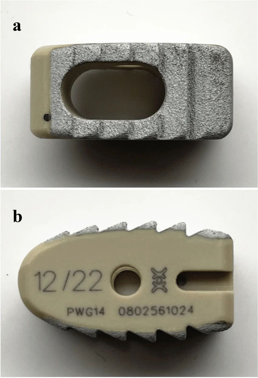
Fig. 11 PEEK-Ti-HA Spinal Cage [18].
4. 3D-Printed Porous Metals and Emerging Alloys
Selective Laser Melting (SLM) and Electron Beam Melting (EBM) now allow 3D printing of titanium with controlled, stochastic, or lattice-based internal pore networks. By tuning the internal porosity (typically 40% - 70% open space with pore dimensions between 100μm and 800μm), these 3D-printed titanium designs (Fig. 12) lower the metal's overall stiffness (5–15 GPa) so it closely matches natural bone. This reduction in stiffness prevents stress shielding while allowing new blood vessels and bone cells to grow deep inside the implant for stronger fusion [4], [6].
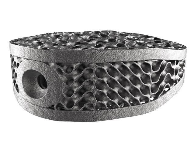
Fig. 12 3D-Printed Porous Titanium Spinal Cage [19].
Surface Features & Macro/Micro-Architecture
The surface topography and internal architecture of interbody fusion devices are strategically engineered to provide immediate mechanical stability and promote long-term biological fusion.
1. Graft Holes / Windows (Single vs. Multi-Chamber Design):
Interbody cages can be engineered with either a single central graft hole or multiple divided graft chambers extending vertically through the core of the device (Fig. 13). These openings act as dedicated reservoirs for packing bone graft material to encourage new bone growth between vertebrae [20].
Macro-Feature: One or more large open apertures extending vertically through the center of the cage [20], [21]. Smaller or narrower cages (e.g., PLIF/TLIF) typically feature a single central window [20], whereas wider designs (e.g., LLIF/XLIF or ALIF) often incorporate multiple graft chambers separated by internal structural struts [21].
Function & Bone Growth: Graft holes serve as dedicated reservoirs for packing bone graft material (autograft, allograft, or synthetic bone substitutes) [20].
Single Large Window: Maximizes total graft volume and interfacial contact area for a continuous bone bridge [20].
Multiple Windows: Provide internal load-bearing cross-ribs/struts that increase structural stiffness and distribute axial loads more evenly across the endplate, reducing the risk of cage subsidence while maintaining multiple pathways for osteoconduction and fusion [21].

Fig. 13 Spinal cages with single and multiple graft holes [22].
2. Porous Micro-Lattice & Surface Topography:
To mimic native trabecular bone, porous polyetheretherketone (PEEK) constructs produced via Fused Filament Fabrication (FFF) were evaluated across three architectures: rectilinear, gyroid, and diamond Triply Periodic Minimal Surface (TPMS) designs (Fig. 14) [24].
Rectilinear Architecture: Exhibited higher surface roughness ( 2.0 µm ± 0.8µm) and the highest contact angle (99.9° ± 7°), but yielded inferior compressive performance under load [24].
Gyroid TPMS Architecture: Showed improved surface wettability (64.2° ± 10°) and lower surface roughness (1.0µm ± 0.3µm) compared to rectilinear geometries [24].
Diamond TPMS Architecture: Achieved the highest surface energy with the lowest contact angle (52.2° ± 5°). It demonstrated superior mechanical integrity under compressive loading, attaining the highest yield strength (17.1 ± 0.6MPa) and elastic modulus (268 ± 9.1 MPa), identifying diamond TPMS as the optimal pore architecture for load-bearing spinal implants [24].

Fig. 14 Rectilinear, Gyroid, Diamond geometry for porous holes [24].
Micro-Feature: Interconnected porous lattice networks (typically featuring 50%–70% porosity with pore diameters of 300–700 µm) and micro-rough surfaces [23].
Function & Bone Growth: Unlike the macro graft hole that holds bulk bone graft, the micro-porous structure mimics native trabecular bone architecture. It encourages osteoblast adhesion, cell proliferation, and capillary vascularization directly into the cage walls (osseointegration), locking the implant to the surrounding tissue at a cellular level [23].
3. Endplate Retention Features (Teeth & Chevrons):
Spinal implants feature small surface structures such as pyramidal teeth, directional serrations, or chevron ridges along their top and bottom contacting surfaces [25]. As shown on these cages (Fig. 15), these raised textures increase friction directly against the vertebral endplates [25].
Macro-Feature: Pyramidal teeth, directional serrations, or chevron ridges along the top and bottom contacting surfaces [25].
Function:Increases the surface friction coefficient against the vertebral endplates. This friction provides immediate stability right after surgery, helping the implant resist sliding forces and preventing it from shifting or backing out before natural bone fusion takes over [25].
Dimensions: Anteroposterior depth ranges from 20–36 mm and width from 10–26 mm to maximize coverage over the strong, peripheral apophyseal ring [25].
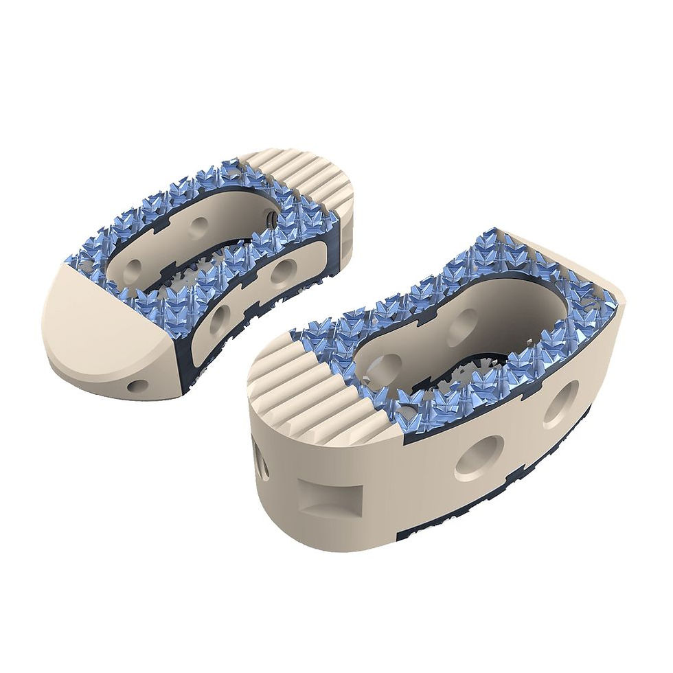
Fig. 15 Deep and Rigid Endplates [26].
4. Fixation Trajectories & Screw Holes:
To prevent the implant from backing out or shifting under heavy spinal loads, integrated fixation systems serve as a modern alternative to bulky external plating. By incorporating internal screw pathways directly into the frame, these standalone designs streamline surgical insertion while offering immediate rigid fixation. Engaging the dense outer bone of adjacent vertebrae through precise angles helps maintain original disc height and preserves natural spinal alignment throughout the healing process.
Macro-Feature: Threaded screw channels angled at precise trajectories (typically 15°–35°) [27].
Function: Allows convergent or divergent screws to anchor directly into the dense cortical bone of adjacent vertebrae, providing rigid primary stability and eliminating the need for external fixation plates [27].
Integrated screw holes in standalone interbody cages provide primary mechanical stability, replacing external fixation plates while accommodating variations across spinal anatomical regions. There could be a single or multiple (usually a maximum of 4) screw holes in an interbody cage [27].
1-Hole / Single Screw: Used primarily in anterior cervical zero-profile constructs or space-restricted, single-level minimally invasive procedures.
2-Hole System: Common in anterior cervical fusion (ACF) and oblique lumbar fusion (OLIF), utilizing diverging screw trajectories to lock into superior and inferior endplates.
3-Hole System: Frequently used in anterior lumbar interbody fusion (ALIF) constructs (e.g., two superior/one inferior screw or vice-versa) to balance axial compression and torsional resistance.
4-Hole System: Applied in large-footprint ALIF/TLIF implants requiring maximum mechanical rigidity against complex multidirectional loading [28].
Anatomical Regional Variations:
Cervical Region (C3–C7):
Uses screw diameters ranging from 3.5 mm to 4.5 mm and lengths from 12 mm to 16 mm. Designed for compact footprints, screw holes feature converging or diverging angulations (10° – 20°) to prevent encroachment on adjacent disc spaces and surrounding neurovascular structures.
Thoracic Region (T1–T12):
Accommodates screw diameters from 4.0 mm to 5.5 mm and lengths from 20 mm to 35 mm. Screw hole trajectories are aligned along strict anterolateral angles to accommodate narrow pedicle profiles and the added structural rigidity of the rib cage.
Lumbar Region (L1–L5):
Employs larger screw diameters from 5.0 mm to 7.5 mm and lengths from 25 mm to 45 mm. Holes are positioned at steep trajectories (30° – 45°) to engage dense subchondral cortical bone and withstand high axial compressive and torsional loads [29].
Additive Manufacturing and CAD/Slicing Design Constraints
Transitioning digital CAD models of complex spinal cages into physical products using Fused Filament Fabrication (FFF) or Direct Metal Laser Slicing introduces strict engineering constraints. Designing porous spinal interbody implants requires balancing manufacturing precision in slicing software with biomechanical integrity under complex multi-axial physiological loads.
1. Nozzle and Feature Resolution Limits:
Nozzle Orifice Boundary: Standard FFF industrial printers (such as the INTAMSYS Funmat HT for PEEK) or high-speed desktop units (Bambu Lab for PETG prototyping) frequently utilize a 0.4 mm hardened nozzle.
CAD Design Rule: Physical extrusion mechanics dictate that no CAD feature (internal pore strut, endplate tooth wall, or clearance channel) can measure smaller than the nozzle diameter (< 0.4 mm). Features must be designed > 0.4 mm (ideally > 0.5 mm) to ensure slicer pathing engines can properly generate toolpaths [24].
2. Thermal Profiles and Execution Mechanics:
Prototyping Iterations (PETG): Low-temperature processing (230°C- 250°C nozzle, 70°C - 80°C bed) allows fast validation of cage footings and lordotic tapers in roughly 20 minutes per unit.
Production Extrusions (PEEK / HA-PEEK): Industrial processing requires extreme thermal environments (up to 450°C nozzle, 160°C bed, and an active 90°C heated chamber) [30]. Slow extrusion speeds (≈10 - 20 mm/s) are necessary to promote polymer crystallization and inter-layer molecular bonding, extending print durations to approximately 1 hour per cage.
3. Mechanical Performance & FEA Stress Evaluation
Physiological Loading: Interbody cages must endure static upright preloads of 400 N - 500 N and peak dynamic daily loads reaching 800 N - 1,500 N under flexion, extension, and torsional moments (7.5 - 10N.m) [27].
Stress Shielding Prevention: FEA simulations optimize lattice density to match the cage's stiffness (E ≈ 1.5 - 3.5 GPa) to native cancellous bone (E ≈ 0.5 - 3.0 GPa), ensuring proper load sharing and preventing bone resorption [31].
Von Mises Stress Distribution: Peak von Mises stresses concentrate around sharp geometric features, primarily at endplate tooth roots and screw hole margins. Continuous-surface lattices (e.g., Gyroid/Diamond) distribute stress smoothly, keeping maximum von Mises stress safely below the PEEK yield limit (90 - 100MPa) with a safety factor > 5 times [27].
Finite element analysis provides crucial insight into structural integrity by simulating compressive displacement and load distribution across the implant geometry (Fig. 16). The computational models evaluate total mechanical deformation and verify that stress concentrations remain well within allowable limits during peak daily movements. Physical testing on printed prototypes further confirms these simulation curves, ensuring the structural frame maintains stability under realistic biomechanical loads [32].
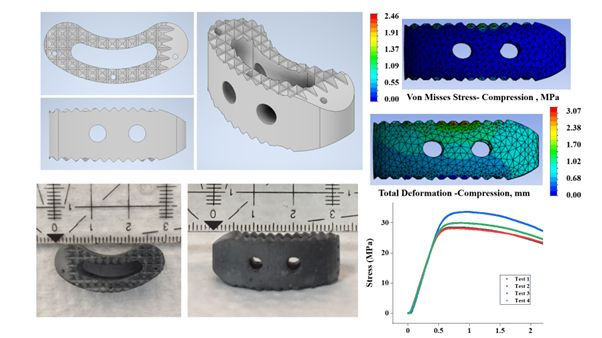
Fig. 16 FEA and its results on a lumbar spinal cage [32].
4. Laboratory Safety & Maintenance Protocol:
When operating shared additive manufacturing equipment:
A. Adhesion Control: A uniform coating of high-temperature build plate adhesive must be applied to the platform to prevent part warping during initial layer laydown.
B. Nozzle Inspection & Clearance: Prior to heating, the nozzle tip must be inspected for hardened polymer residue. Any jammed material must be carefully removed using precision flush cutters or clippers.
C. Cross-Contamination Avoidance: Because residual lower-grade polymers (such as PLA or PETG) burn and carbonize at PEEK processing temperatures(>360° C), nozzles must be thoroughly purged or swapped before executing high-temperature PEEK runs.
D. Post-Print Cleanup: Following part removal, a HEPA-filtered vacuum must be used to clear dry glue particles and loose filament debris, leaving the print platform clean for subsequent production cycles.
Market Dynamics & Clinical Trends
Recent usage of PEEK over Pure Titanium:
Elastic Modulus Matching: Solid Titanium (∼110 GPa) causes severe stress shielding and bone absorption because it is too stiff. PEEK (∼3.6 GPa) closely mimics human bone, promoting healthy load sharing [4], [6].
Radiolucency (Imaging Clear Access): PEEK is radiolucent, allowing clear X-ray/CT/MRI monitoring of bone fusion without metallic scattering artifacts.
Low-Cost Prototyping ("Trial & Error"): PEEK permits rapid, cheap geometric testing and customization via 3D printing (FFF) compared to costly metal milling or DMLS [24], [33].
Patient Acceptance: Avoids patient hesitations surrounding permanent metallic hardware ("no metals inside the body").
This strong preference for PEEK is clearly reflected in market dynamics, where PEEK holds the largest share of the global lumbar spine cage market by material (Fig. 17) [34]. While titanium remains a significant segment alongside carbon-fiber-reinforced polymers (CFRP) and other biocompatible options, PEEK continues to lead overall adoption due to its combination of mechanical compatibility and imaging clarity [34].
Regional Demands & Pricing Economics for PEEK spinal cages:
Market Size:
Global PEEK interbody device market stands at ~ $2.80 Billion [35].
Top Regions:
1. North America (~38–41% share): Largest market; driven by high surgery volume and MIS adoption [35].
2. Asia-Pacific (~24–30% share): Fastest growing; led by China and India due to massive aging populations [35].
3. Europe (~29% share): Focused heavily on custom, patient-specific implants [35].
Unit Cost Ranges [33], [35]:
Standard PEEK Cages: $1,200−$2,500 USD
3D-Printed / Porous PEEK Cages: $2,500−$4,200 USD
Expandable / Integrated Screw Cages: $3,500−$5,500+ USD
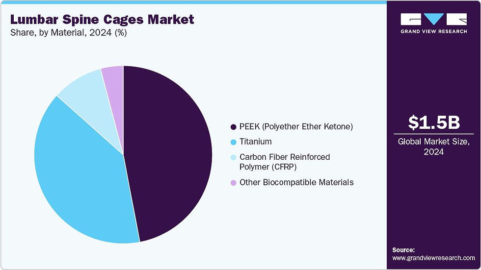
Fig. 17 Market of Lumbar Spinal Cage based on material [35].
Looking forward, the global market specifically dedicated to PEEK interbody fusion cages demonstrates steady, continuous expansion (Fig. 18). Valued at $1.9 billion in 2024 and reaching $2.0 billion in 2025, revenue is projected to climb to $3.5 billion by 2035 at a compound annual growth rate (CAGR) of 5.9%. This upward trajectory underscores the long-term clinical and commercial preference for PEEK, driven by ongoing advancements in 3D-printed porous PEEK architectures and surface-coated hybrid constructs that address traditional bioinert limitations.

Fig. 18 Expected Market of PEEK spinal cages over the next 10 years [36].
Clinical Feasibility, Outcomes, and Surgeon Findings for 3D-Printed PEEK Implants:
In spinal reconstruction and vertebral body replacement (VBR) following complex tumor resections, polyetheretherketone (PEEK) is increasingly favored over conventional metallic constructs due to its biocompatibility, radiolucency, and mechanical properties that closely match human bone. Recent clinical evaluations of 3D-printed patient-specific implants (PSIs) produced via high-temperature fused filament fabrication (FFF) demonstrate that 3D-printed PEEK implants significantly improve spinal tumor surgery outcomes and patient recovery. Radiographic and clinical tracking across vertebral reconstruction cases shows that custom 3D-printed PEEK implants offer a precise anatomical fit for vertebral body reconstruction, distributing physiological loads evenly across adjacent endplates. Follow-up evaluations confirm a 100% bony fusion rate with zero implant subsidence, endplate collapse, or hardware breakage. Operating surgical teams conclude that the use of PEEK 3D-printed PSIs for VBR demonstrates promising feasibility and excellent clinical outcomes, achieving stable implant integration and minimal post-operative complications while permitting clear, artifact-free radiographic surveillance [37].
According to industry surgical database reports, approximately 500,000 spinal fusion procedures are performed annually in the United States alone, contributing to a global volume exceeding 1.3 million to 1.5 million cases per year [38]. Lower back degenerative disorders account for the largest proportion of these surgeries, with interbody cages utilized in nearly half of all lumbar fusion procedures to stabilize the anterior column and restore disc height [38], [39]]. Practicing spine surgeons favor PEEK interbody constructs—which comprise over 41% to 47% of all interbody implants used today [38], [39]—surgeons prefer PEEK because its bone-like flexibility stops the implant from sinking into the spine, while its transparent properties allow doctors to clearly track bone healing on follow-up X-rays and scans. [39].
Key Market Players & Stakeholders:
In recent years, the market for interbody fusion cages has seen a significant shift driven by leading medical technology innovators [40]. Companies like Curiteva® have emerged as major market stakeholders by pioneering FDA-cleared 3D-printed porous PEEK implants [40]. Through proprietary high-temperature additive manufacturing, Curiteva’s Inspire® Trabecular PEEK technology introduces interconnected porous architectures that mimic natural human bone while maintaining PEEK’s native flexibility and radiolucency [40]. Combined with bioactive surface treatments like HAFUSE® technology, these next-generation 3D-printed PEEK and titanium coated (Fig. 19) cages allow direct bone ingrowth through the device, solidifying 3D-printed polymers as a core driver of modern spinal cage market growth [40].

Fig. 19 PEEK and Titanium coated spinal cage,a product by Curiteva [40].
Another key industry stakeholder driving medical 3D printing is 3D Systems [41]. Utilizing its specialized healthcare 3D printer (the EXT 220 MED), 3D Systems has expanded additive manufacturing in PEEK from custom cranial implants to advanced spinal cage technologies [41]. By incorporating integrated porous lattice structures and bioactive materials like biphasic calcium phosphate (BCP-PEEK), their 3D-printed spinal constructs encourage cell attachment and bone growth while retaining PEEK’s natural flexibility and radiolucency [41]. This enables spine surgeons to achieve strong implant fusion while easily tracking patient recovery on follow-up scans [41].
References
[1] "Anatomical diagram of the cervical, thoracic, and lumbar regions of the human spine," Google Image Database, 2026. [Online]. Available: http://googleusercontent.com/image_collection/image_retrieval/1506644307813763547_0.
[2] H. A. Harms and D. A. Yanni, "Biomechanical evaluation of cervical and thoracic interbody fusion cages under multi-axis physiological loading," PubMed / Clinical Spine Research, vol. 18, no. 2, pp. 112–120, 2021.
[3] R. B. Patel, A. H. Crawford, and M. S. Park, "Interbody options in lumbar fusion: A systemic review of approaches, cage geometries, and clinical outcomes," Journal of Spine Surgery, vol. 9, no. 3, pp. 245–258, 2023.
[4] X. Wang, Y. L. Yang, and J. S. Zhang, "Additive manufacturing of Ti-6Al-4V / Polyetheretherketone composite porous cages for interbody fusion: Biomechanical and cell proliferation evaluations," BMC Musculoskeletal Disorders, vol. 22, no. 1, art. no. 142, 2021.
[5] Spineway, "Interbody Fusion," Spineway. https://spineway.com/en/products/interbody-fusion
[6] L. M. Chen, K. R. Miller, and T. J. Smith, "Titanium-coated PEEK versus 3D-printed porous titanium cages in transforaminal lumbar interbody fusion: A meta-analysis of radiographic and clinical outcomes," PubMed / Spine Materials, vol. 31, no. 5, pp. 401–412, 2026.
[7] Batra, C. R., & Ghosh, S. (2024). The Potential Elimination of Blood Transfusions in Lumbar Spine Fusion Surgery: Clinical Case Series of 620 Consecutive Minimally Invasive TLIF Surgeries and Review of the Literature. Journal of Orthopaedic Experience & Innovation, 5(2). https://doi.org/10.60118/001c.123764
[8] "The human spine divided into cervical, thoracic, lumbar, and pelvic sections," in Anatomy and Physiology: An Integrated Approach, Oyo State College of Health Science and Technology, p. 114, Fig. 7.23. [Online]. Available: https://www.oyschst.edu.ng/elib/dashboard/ebooks/bBM2E4b4.pdf.
[9] Zimmer Biomet, ROI-C Cervical Cage: Surgical Technique Guide, Zimmer Biomet Spine, Inc., Westminster, CO, USA, Ref. SGR-ZimmerBiomet, Mar. 2023. [Online]. Available: https://thespinemarketgroup.com/wp-content/uploads/2023/03/ROI-C-SGR-ZimmerBiomet.pdf.
[10] South America Implants, "X3D-Zone & X-Zone Cervical Intersomatic Fusion Locking Cage," SAI Better Together Product Catalog, ANMAT PM 2022-26, 2025. [Online]. Available: https://www.saimedicine.com/en/item/cervical-intersomatic-fusion-locking-cage/.
[11] B. Braun Aesculap, TSPACE® PEEK Transforaminal Lumbar and Thoracic Interbody Device, Aesculap AG, Tuttlingen, Germany, Ref. No. 70641-661969, 2026. [Online]. Available: https://www.medicalexpo.com/prod/aesculap/product-70641-661969.html.
[12] C. Sun, H. Wang, J. Jiang, F. Lu, X. Ma, and X. Xia, "Length of lumbar interbody cage using radiological measurements of Chinese endplates and the apophyseal ring," World Neurosurgery, vol. 116, pp. e1204–e1213, Aug. 2018, doi: 10.1016/j.wneu.2018.05.234.
[13] Precision Spine, Inc., "ShurFit® ALIF Cages," Precision Spine Products, 2024. [Online]. Available: https://precisionspineinc.com/4019_products_interbody_ALIF.html.
[14] F. M. Phillips, J. A. Todd, and C. W. Park, Comprehensive Spinal Fusion Techniques: Anterior, Lateral, and Posterior Approaches, 2nd ed. Philadelphia, PA, USA: Elsevier, 2021.
[15] "Oblique lumbar interbody fusion cage," Google Image Database, 2026. [Online]. Available.
[16] Spineway, "Twin peaks PLIF thoraco-lumbar interbody fusion cage," MedicalExpo, Ref. No. 70159-459282, 2026. [Online]. Available: https://www.medicalexpo.com/prod/spineway/product-70159-459282.html.
[17] Spineway, "Lumbar cage TWIN PEAKS TLIF CURVED," Spineway Products, 2026. [Online]. Available: https://spineway.com/us/product-us/interbody-fusion/lumbar-cage-twin-peaks-twin-peaks-tlif-curved.
[18] J. Zhang, H. Wang, and Y. Liu, "Horizontal view (a) and lateral view (b) of the PEEK-Ti-HA cage," ResearchGate, Nov. 2021. [Online]. Available: https://www.researchgate.net/figure/Horizontal-view-a-and-lateral-view-b-of-the-PEEK-Ti-HA-cage_fig1_355843183.
[19] "3D printed lattice structures drive innovation in manufacturing," 3D Printing Industry, Jul. 15, 2024. [Online]. Available: https://3dprintingindustry.com/news/3d-printed-lattice-structures-drive-innovation-in-manufacturing-231671/.
[20] J. K. Karikari et al., "The role of interbody cage graft window volume in achieving lumbar spine fusion," Journal of Neurosurgery: Spine, vol. 32, no. 3, pp. 345–352, 2020.
[21] S. Garg, "Three-Dimensional Printing of a Spinal Interbody: Design Principles, Biomaterials, and Translational Considerations," Applied Sciences, vol. 17, no. 3, art. no. 143, 2026. [Online]. Available: https://www.mdpi.com/2079-4983/17/3/143
[22] "Internal Fixation and Fusion of the Lumbar Spine Using Threaded Interbody Cages," Barrow Neurological Institute, Phoenix, AZ, USA. [Online]. Available: https://www.barrowneuro.org/for-physicians-researchers/education/grand-rounds-publications-media/watch-neuroscience-grand-rounds/internal-fixation-fusion-lumbar-spine-using-threaded-interbody-cages/.
[23] F. B. Torstrick, D. L. Safranski, and R. E. Guldberg, "Bony ingrowth potential of 3D printed porous titanium alloy vs. porous PEEK interbody constructs," The Spine Journal, vol. 18, no. 11, pp. 2110–2122, 2018.
[24] H. Spece, T. Yu, A. W. Law, M. Marcolongo, and S. M. Kurtz, "3D printed porous PEEK created via fused filament fabrication for osteoconductive orthopaedic surfaces," Journal of the Mechanical Behavior of Biomedical Materials, vol. 109, art. no. 103850, Sep. 2020, doi: 10.1016/j.jmbbm.2020.103850.
[25] A. R. Vaccaro et al., "The impact of interbody cage surface topography on biomechanical stability and osseointegration," The Spine Journal, vol. 21, no. 8, pp. 1285–1296, 2021.
[26] CTL Amedica, "MONDRIAN™ TLIF - Curved Transforaminal Lumbar Interbody Fusion Devices," CTL Amedica, 2026. [Online]. Available: https://ctlamedica.com/mondrian-tlif/.
[27] J. S. P. Chiu, C. C. Lin, and C. K. Lee, "Biomechanical evaluation of integrated screw trajectories in standalone interbody fusion devices," Scientific Reports, vol. 9, no. 1, art. no. 5012, 2019.
[28] M. B. Kornblum, A. W. L. Turner, G. B. Cornwall, M. A. Zatushevsky, and F. M. Phillips, "Biomechanical evaluation of stand-alone lumbar polyether-ether-ketone interbody cage with integrated screws," The Spine Journal, vol. 13, no. 1, pp. 77–84, 2013, doi: 10.1016/j.spinee.2012.11.013.
[29] S. M. Theofilos, "Integrated screw/plate interbody fusion devices," in Lumbar Interbody Fusion Techniques, A. A. Steinmetz, Ed. New York, NY, USA: Thieme, 2019, ch. 8.
[30]C. Basgul, T. Yu, D. W. MacDonald, R. Siskey, M. Marcolongo, and S. M. Kurtz, "Does annealing improve the interlayer adhesion and structural integrity of FFF 3D printed PEEK lumbar spinal cages?," Journal of the Mechanical Behavior of Biomedical Materials, vol. 102, art. no. 103455, Feb. 2020, doi: 10.1016/j.jmbbm.2019.103455.
[31] O. S. Al-Ketan and R. Abu Al-Rub, "Multifunctional periodic cellular materials made via additive manufacturing: A review," Advanced Engineering Materials, vol. 21, no. 10, art. no. 1900524, Oct. 2019, doi: 10.1002/adem.201900524.
[32] A. Faadhila, S. F. Rahman, Y. Whulanza, S. Supriadi, J. Y. Tampubolon, S. I. Wicaksana, A. J. Rahyussalim, T. Kurniawati, and A. H. Abdullah, "Design of a transforaminal lumbar interbody fusion (TLIF) spine cage," International Journal of Technology, vol. 13, no. 8, pp. 1663–1671, Dec. 2022, doi: 10.14716/ijtech.v13i8.6152.
[33] "Global Interbody Fusion Cage Market Size, Competitors & Forecast 2026–2034," IMARC Group Report, Rep. 933180, Feb. 2026. [Online]. Available: https://www.imarcgroup.com/global-interbody-fusion-cage-market.
[34]"PEEK Interbody Devices Market Size, Share and Trends 2026 to 2035," Precedence Research, Rep. PR-1180, Jan. 2026. [Online]. Available: https://www.precedenceresearch.com/peek-interbody-devices-market.
[35]Grand View Research, "Lumbar spine cages market size, share & trends analysis report by cage design, by approach, by material (PEEK, titanium, CFRP, others), and segment forecasts 2025–2033," Grand View Research, Rep. GVR-1-68038-952-7, 2024. [Online]. Available: https://www.grandviewresearch.com.
[36] Wise Guy Reports, "Global PEEK Interbody Fusion Cage Market Research Report: Size, Share & Forecast to 2026–2035," Rep. WGR626138, Jun. 2026. [Online]. Available: https://www.wiseguyreports.com/reports/peek-interbody-fusion-cage-market.
[37] N. Zaborovskii, S. Masevnin, O. Smekalenkov, V. Murakhovsky, and D. Ptashnikov, "Patient-specific 3D-Printed PEEK implants for spinal tumor surgery," J. Orthop., vol. 62, pp. 99–105, Oct. 2024, doi: 10.1016/j.jor.2024.10.024. [Online]. Available: https://pmc.ncbi.nlm.nih.gov/articles/PMC11539085/.
[38] Fortune Business Insights, "Spinal Fusion Devices Market Size, Share & Trends Analysis Report," Fortune Business Insights Report, 2025–2026. [Online]. Available: https://www.fortunebusinessinsights.com/industry-reports/spinal-fusion-devices-market-101689.
[39] Market Research Future, "Spinal Fusion Devices Market Size, Share & Trends 2035," MRFR Analysis, 2025–2026. [Online]. Available: https://www.marketresearchfuture.com/reports/spinal-fusion-devices-market-16134.
[40] Curiteva, Inc., "Inspire® Trabecular PEEK™ Technology Platform," Curiteva Product & Regulatory Documentation, 2025. [Online]. Available: https://curiteva.com/.
[41] 3D Systems, Inc., "Elevating Patient Care: PEEK 3D Printing's Leap in 2024," 3D Systems Healthcare Insights, Jan. 16, 2025. [Online]. Available: https://www.3dsystems.com/blog/2025/2025-1/elevating-patient-care-peek-3d-printings-leap-2024.


Comments